DIY 3D-Printed Tracked Mobile Robot
DZ01 | Domechy Project Library
Problem Statement
Most beginner robotic kits on the market focus heavily on electronics and software, while the mechanical parts are kept simple. That makes sense considering the goal of these kits is to teach coding and circuit connection.
But robotics is more than just circuits and code. The mechanical side is just as important, and in my opinion, it should look cool too.
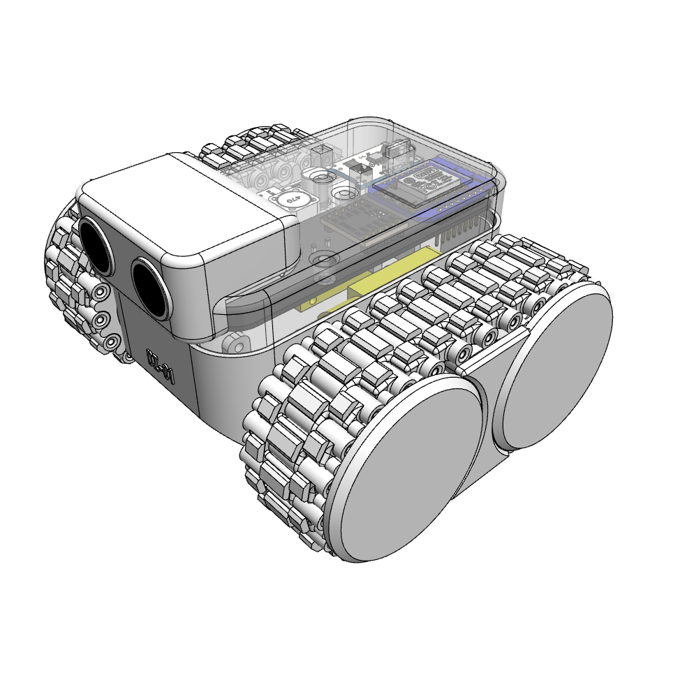
So, my goal with this project was to design a DIY 3D printed tracked robot (DZ01) that isn’t only functional, but also visually pleasing — something that feels more exciting than the standard starter kits.
What Makes a Robot?
To simplify: a robot is a machine that can “think” on its own.
A radio-controlled car has motors and servos, but it only moves when you push buttons. Without you, it does nothing.
A robot, on the other hand, follows a program. Press a button and it runs code inside its “head” (microcontroller), which tells it what to do.
For example:
If programmed to move forward unless there’s an obstacle within 50mm, it will keep driving until its ultrasonic sensor detects something closer than 50 mm.
At that point, the code tells it to stop — automatically, without your remote.
That’s what makes it a robot: the ability to act based on programmed logic and sensor feedback.
Core Components of the Robot
Microcontroller (acting as the brain)
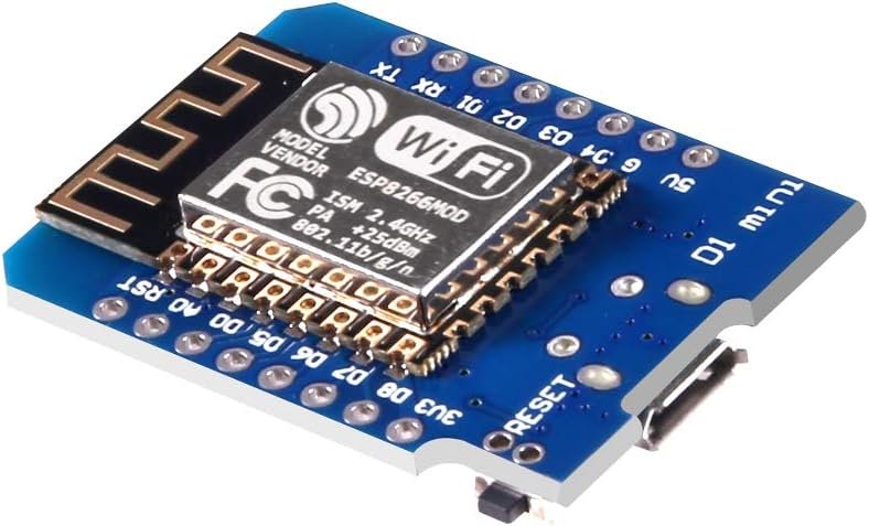
WeMos D1 Mini → runs the robot code
Actuators
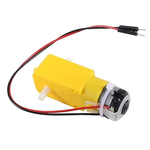
2× DC Motors → drive the tracks
Motor Driver
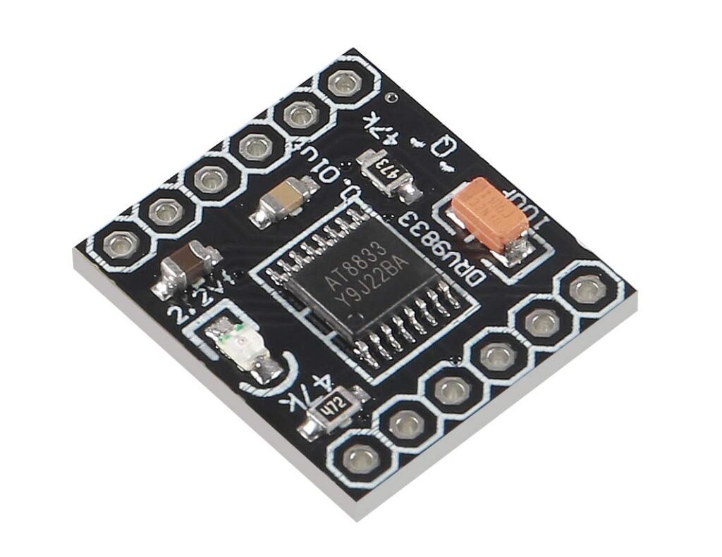
DRV8833 → controls current & speed of DC motors
Sensor
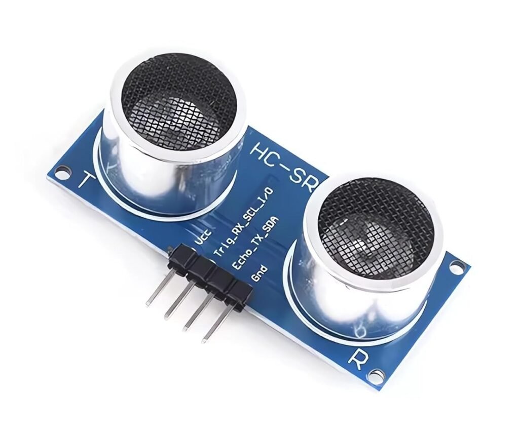
HC-SR04 Ultrasonic Sensor → detects obstacles
Power
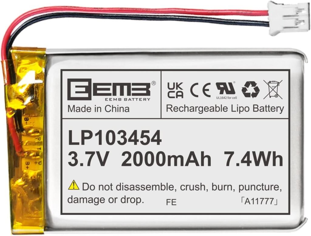
3.7V 2000 mAh LiPo Battery → rechargeable supply
Supporting Components
- XL6009 Boost Converter → steps up the 3.7 V battery to ~5 V, which most components need.
- TP4056 Charging Module → allows USB-C charging for the battery.
- Power Switch → lets me cut the power easily.
And of course, to bring everything together: mechanical parts — body, frame, cover. That’s where mechanical design really matters.
Mechanical Design
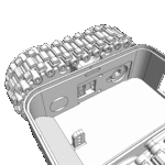
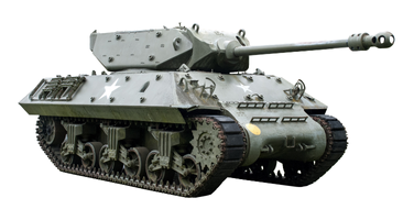
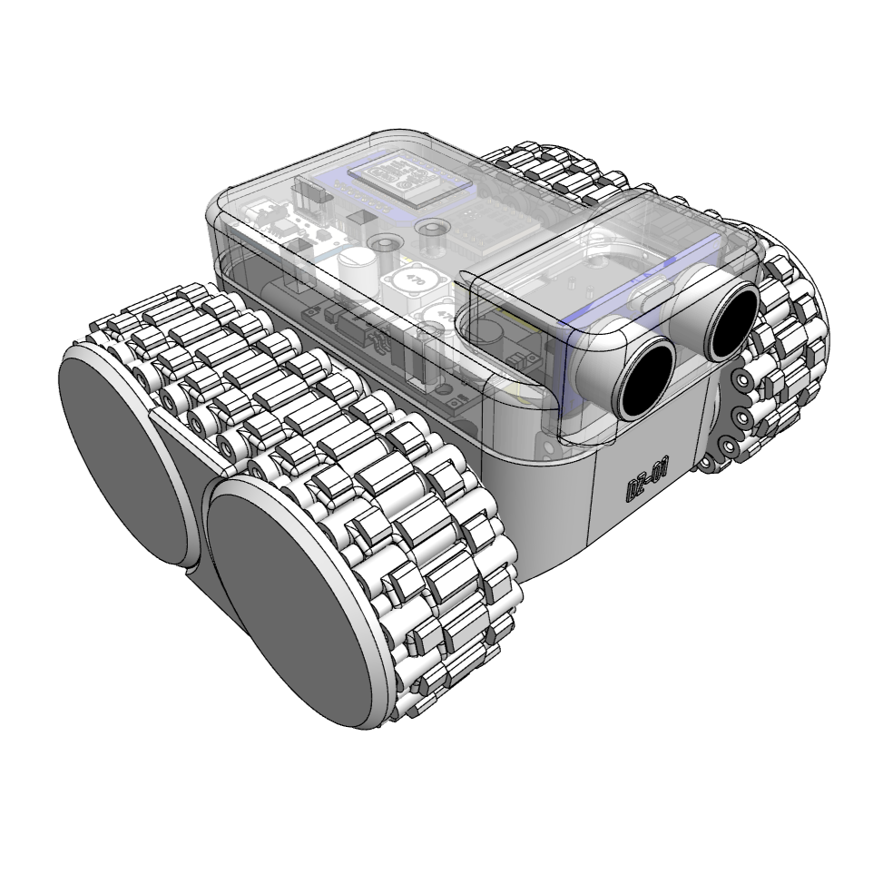
I wanted this robot to look like a mini-tank, because tanks are cool and tracks make them even cooler.
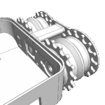
The track system was designed based on my 3D-printed sprocket & track unit (documented separately on design library, learn more about it here).
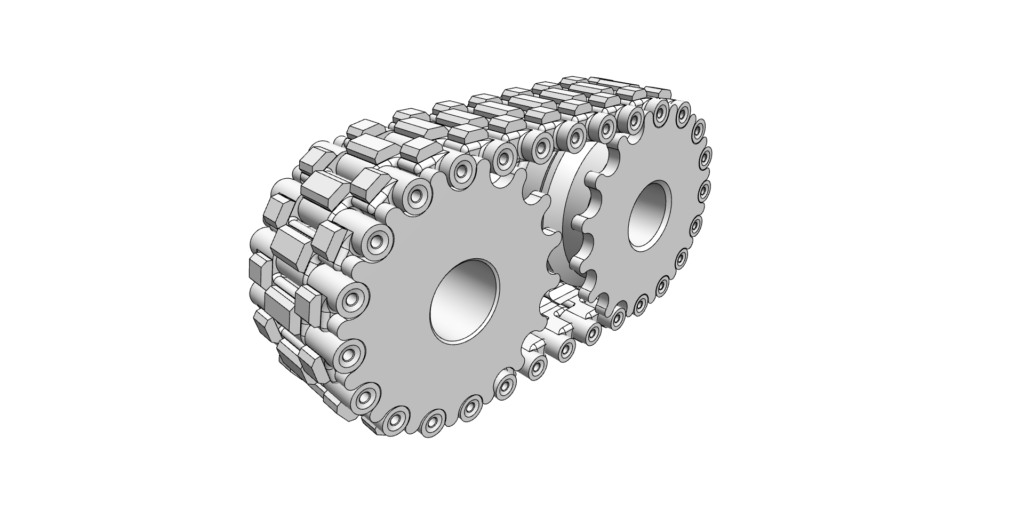
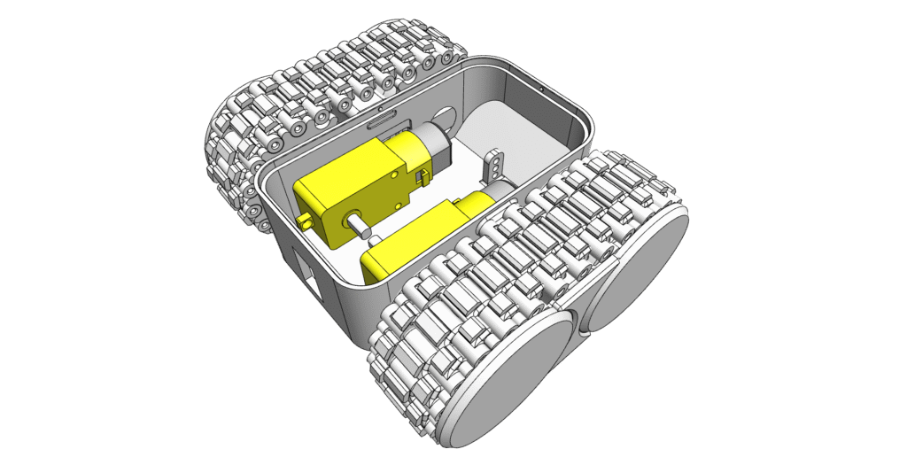
- The drive sprockets are connected to the motors, while idler sprockets rotate freely on shafts.
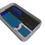
- The robot frame houses the electronics: motors, battery, and switch.
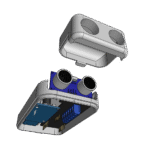
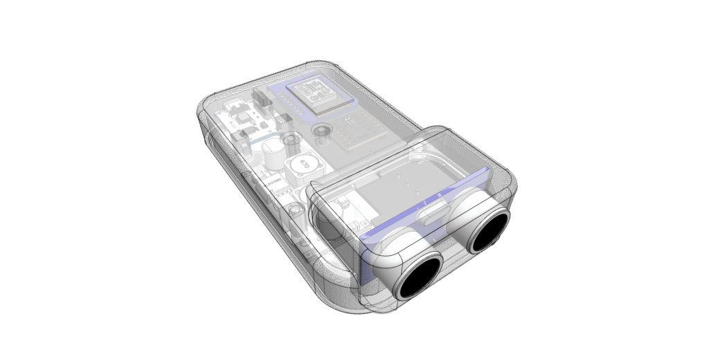
- A cover shell holds the rest of the components.
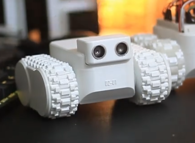
- I even added a small “head” for the ultrasonic sensor, so it doesn’t look bare like most starter kits.
Custom PCB
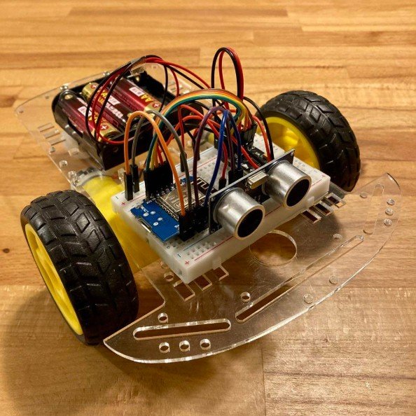
During prototyping, I used a breadboard and jumper wires — flexible, but bulky and messy.
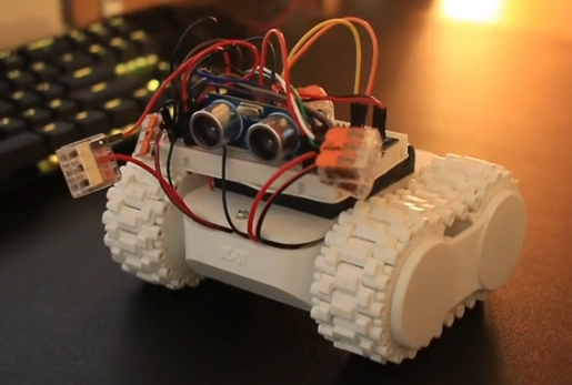
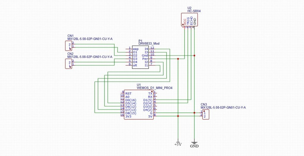
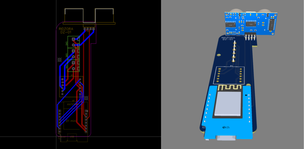
To clean things up, I designed a simple custom PCB to integrate the microcontroller, motor driver, and sensor connections. I’m not an electronics guy, but after some YouTube studying, I managed to design something that worked.
Special thanks to PCBWay for sponsoring the board. Without their help, I probably wouldn’t have tried PCB design at all.
Final Result
The finished robot came out just as I imagined — compact, neat, and functional.
The files are available if you want to try building your own:
STL files (3D-printable parts)
Gerber file (for fabricating the PCB)
Problems & Future Improvements
This was my first attempt at creating a mobile robot kit. Since my background is mainly in industrial robotics instead of product design, I can already see plenty of areas to improve when working on a smaller product like this.
Fewer fasteners → A snap-fit design (like LEGO) would make assembly easier for beginners.
Modular PCB → Use header pins instead of soldering components directly, so they can be replaced or upgraded.
Component layout → Right now, some electronics are in the base and others in the cover, which makes maintenance harder. In the next version, I’d like everything accessible from one side.
Even with these weaknesses, I’m satisfied with the result. The robot works, looks cool, and taught me a lot.
