DIY Clap-Activated LED Light
Domechy Project Library | DZ00

Problem Statement
I wondered what it takes to create an LED light that can be turned on and off by a clap. Having no prior experience in electronics, I decided to design and build a 3D-printed clap-activated LED light.
How Does It Work?
A normal LED light turns on when current flows through it. If we connect a battery directly, it will stay on until the battery dies. By adding a switch, we can open and close the circuit, turning the LED on and off.
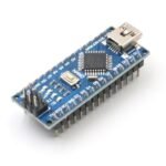
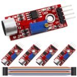
Now, instead of a physical switch, I used a microcontroller + sound sensor. The sound sensor converts sound waves into electrical signals. The Arduino continuously checks this signal and only triggers the LED when the sound exceeds a set threshold. A clap produces a strong enough sound spike, so the Arduino recognizes it and switches the LED on or off.
That’s how a clap-activated LED light works.
Supporting Components
AC-DC Adapter – converts 110V/240V AC to 5V DC
Resistor (220 Ω)
Capacitor (1000 µF, 6.3V)
Mechanical Design
I designed two 3D-printed parts that form the word 作 (saku), which means “to create” or “to build.”
Base: Holds the LED strip around the inner wall. The lower and upper parts have different thicknesses to stop the cover from sliding all the way through.
Cover: Designed 0.2 mm smaller than the base’s inner diameter so it fits snugly but doesn’t fall through.

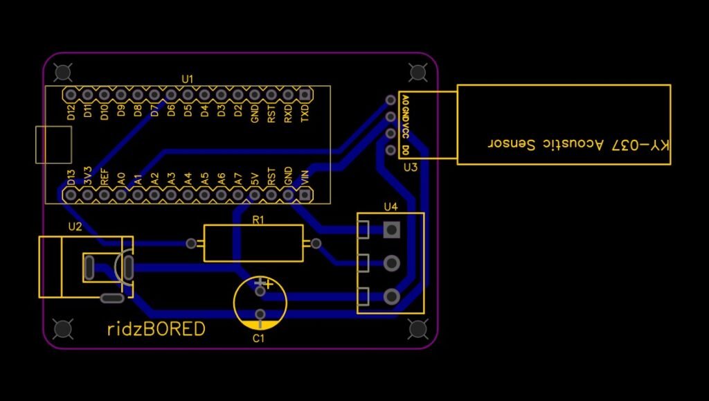
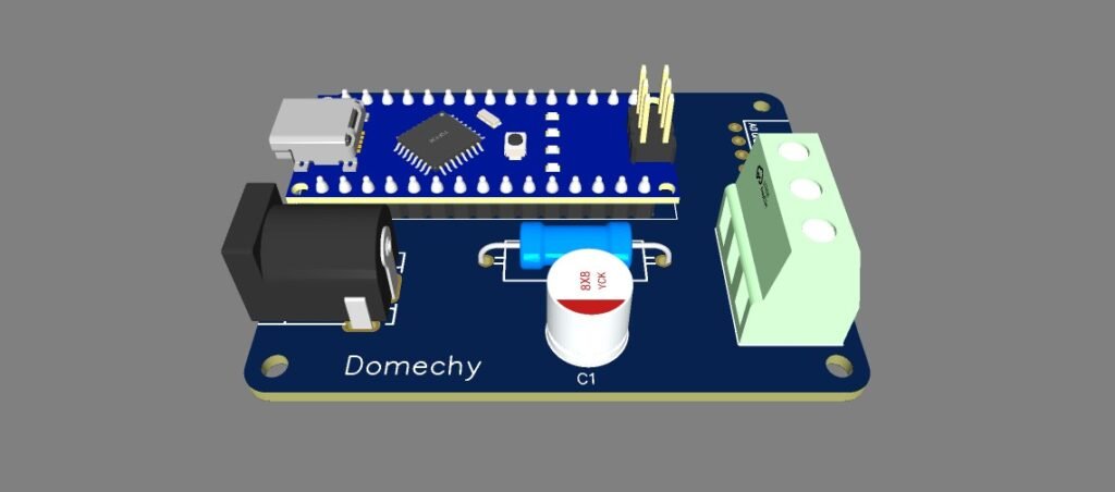
Custom PCB
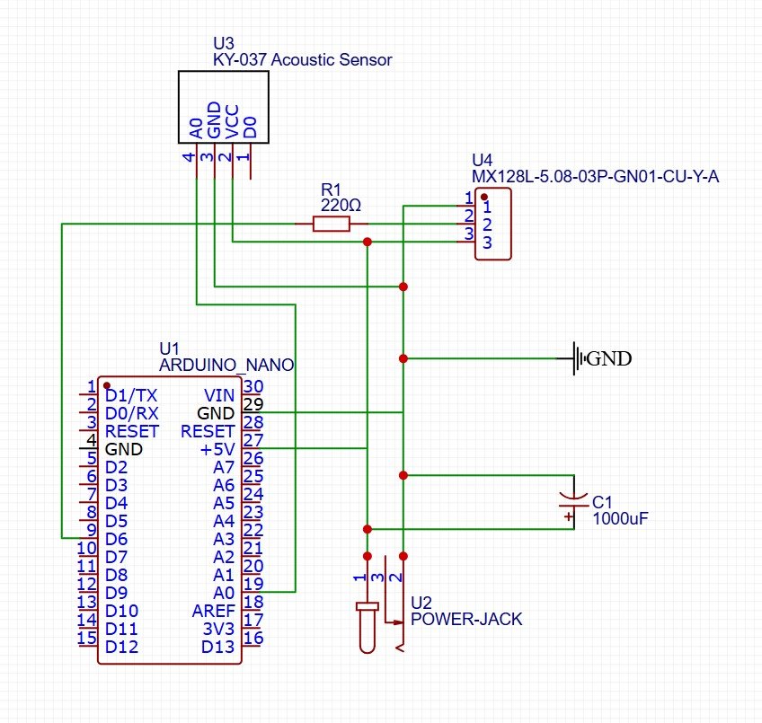
This was the key to the project. A breadboard with jumper wires was too bulky and messy to fit inside the housing. Thanks to PCBWay for sponsoring the PCB — it simplified everything into a single compact board.
Programming
The Arduino code listens to the sound sensor and toggles the LED strip when a clap is detected.
#include
#define SOUND_SENSOR_PIN A0
#define LED_PIN 6
#define NUM_LEDS 70
#define SOUND_THRESHOLD 540
#define BRIGHTNESS 150 // Lower brightness (0-255)

Adafruit_NeoPixel strip = Adafruit_NeoPixel(NUM_LEDS, LED_PIN, NEO_GRB + NEO_KHZ800);

bool ledsOn = false;
bool soundExceededThreshold = false;

void setup() {
  Serial.begin(9600);
  strip.begin();
  strip.setBrightness(BRIGHTNESS); // Set brightness to lower level
  strip.show(); // Initialize all pixels to 'off'
}

void loop() {
  int soundValue = analogRead(SOUND_SENSOR_PIN);
  Serial.println(soundValue); // Print the sound value for debugging

  if (soundValue > SOUND_THRESHOLD) {
    if (!soundExceededThreshold) {
      ledsOn = !ledsOn;
      soundExceededThreshold = true;
    }
  } else {
    soundExceededThreshold = false;
  }

  if (ledsOn) {
    turnOnLeds();
  } else {
    turnOffLeds();
  }

  delay(50); // Small delay to avoid rapid flickering
}

void turnOnLeds() {
  for (int i = 0; i < NUM_LEDS; i++) {
    strip.setPixelColor(i, strip.Color(255, 120, 0)); // Set color to white
  }
  strip.show();
}

void turnOffLeds() {
  for (int i = 0; i < NUM_LEDS; i++) {
    strip.setPixelColor(i, strip.Color(0, 0, 0)); // Turn off LED
  }
  strip.show();
}
Final Result
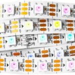
The LED lights up when I clap in front of the sensor. Surprisingly, it even works from a few meters away. By tweaking the Arduino code, the LED strip can also change colors based on different triggers.
You can watch the video of this project here.
Problems & Improvement Ideas
The sound sensor isn’t very accurate. Sometimes it reacts to background noise, and lowering the sensitivity makes it harder to detect claps.
In future iterations, I would consider using a MAX9814 microphone module for more reliable sound detection, or even explore a voice recognition module for spoken commands.
Lessons Learned
This was my first personal electronics project, and I learned a lot about voltage and current requirements.
The power source must match the voltage (in this case, 5V DC from the adapter).
The supply must provide enough current for all components combined, or risk overheating and failure.
Always choose a power supply that can handle slightly more current than required.
